Electric double-layer capacitors( EDLC capacitor ) for power are intended for applications that require discharge currents in the range from mA to A. The characteristics of the capacitors include such performance as relatively high capacitance and low internal resistance, which is applicable to class 3 of the measurement classification specified in IEC 62391-1.
The definition of power density and its calculating procedure should be in accrodance with Annex A.
Annex A.
(informative)
Calculation procedure for power density
A.1 Scope
Annex A specifies definition and calculation procedure of the power density.
A.2 Definition of power density
Power indicates the electric power that can be taken from a capaciotor, expresssed in watts(W).Power density indicates the electric power that can be taken out per mass(or volume) of a capacitor. The higher the power density is, the higher current can be taken efficiently.
A.3 Calcaulation procedure for power density
A3.1 calculation method for power density per mass
a) Measure the internal resistance specified in scetion 4.6.2 of IEC 62391-1.
b) Calculate discharge current value I where U6 is 20%(0.2×U)of the charge voltage by the following formula(see figure A.1)
I=U6/Rd
where Rd is the internal resistance obtained by d.c resistance method.
c) The power density per mass Pd is calculated by the following formula
Pd=1/2×(U-U6+Ue)×Im=(0.12×U2IIRd)
Where
Pd is power density per mass(W/kg);
U is the charge voltage(V);
U6 is drop voltage(V),which is 20%(0.2U)of the charge voltage;
Ue is 40%(0.4U)of the charge voltage(V);
I is the discharge current calculated in A.3.1 b)(A);
Rd is the internal resistance(Ω)obtained by d.c resistance method;
m is the weight of a capacitor(kg);
A.3.2 Calculation method of power densisty per volume
Indication of the power density per volume of a capacitoe is calculated by replacing the mass of the capacitor in A.3.1 C) with the capacitor volume.
Note The capacitor volume here is calculated from nominal demensions of the capacitor,expressed in litres(L)
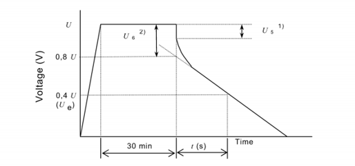
1) The drop voltage does not indicate the voltage U5 that drops instantaneously at the time of the discharge start, but the dropped voltage U6 obtanined from the intersection of the auxillary line extended from the straight part and the time base at the time of discharge start.
2) Where discharge current I is specified in detail specification,U6 is not necessarily 0.2×U
Figure A.1 – Voltage characteristics between capacitor terminals
About SPS
Supreme Power Solutions Co., Ltd. (SPS) is a leading manufacturer of ultracapacitors, as well as a provider of ultracapacitor energy storage systems and technological solutions. Our products have wide industry applications, such as new energy vehicles, wind turbines pitching control systems, trams and subways, smart grid, micro grid, heavy duty machineries, intelligent instrument, etc. We support more than 200 customers, and our products are exported to 26 countries and territories.
More information:https://www.spscap.com
